MSP430G2201 Counter
This article reuses the small ‘roundpcb’ testboard previously featured in the blinky demo to investigate Timer-A0 using Mecrisp-Across. Bitfields.fs is used to supply the register names needed in the configuration and demonstrate the syntax.
The Program
All it does is configure the timer to run freely, then reads it eight times to see how the values change.
No big deal ?
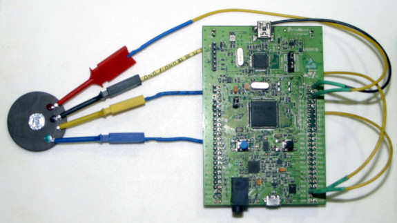
Bear in mind that the MSP430 terminal I’m using actually doesn’t exist, the terminal is a emulation of a MSP430 terminal generated by Mecrisp-Across running under Mecrisp-Stellaris on a STM32F407 Discovery board as in the picture above.
In fact the Target MSP430 MCU doesn’t even HAVE a USART for a terminal of its own!
Mecrisp-Across supplies the emulated terminal, and using JTAG (the 4 wires in the pictures above) reads and writes registers on the MSP430 target.
Source Code
Those who read my Mecrisp-Stellaris Doc site will know that I’m a technician who programs, not a programmer.
Technicians have completely different goals to programmers, we design and fix hardware and programming is only a small part of the overall task for us.
As such I value the following attributes in my source code, stated in order of importance.
Readability
Maintainability
Traceability
Serviceability
Attribute |
Description |
|---|---|
Readability |
No clever code, no magic numbers. This readability is for technicians like me. |
Maintainability |
10 years later, when the device is broken in some way, it needs to be fixed, the code has to make this part easy, not harder. |
Traceability |
Register names have to be MCU manufacturer technical manual compliant so hours don’t have to be wasted decoding ‘magic numbers’ and what they mean. |
Serviceability |
The source should have built in Test Words, such as make a stepper motor rotate once, clockwise, just to test it isn’t jammed. |
IMPORTANT NOTE: Although the MSP430G2201 target has only 2KB of flash, the source doesn’t have to be made into the smallest size to fit because its running in the EMULATOR which has 64KB of ‘flash’. Mecrisp-Across is possibly one of the strongest optimizing Forth cross compilers you have ever seen. Out of the box, it does
Constant folding
Register allocation for both data and return stack
Dead code elimination (imagine a constant feed into case)
Register allocation across control structures
Determination which definitions are in use,
Automatic inlining of definitions used one time only
Interrupt handler framing depending on register usage
Finally, the Target binary image will be compiled to machine code before it’s flashed. This results in a tiny bootable image, for instance only 58 bytes for a Blinky.
Source Description
A BIG THANK YOU to Vadzim Dambrouski, https://github.com/pftbest/msp430_svd, who took DSlite files released by TI and processed them with the Rust programming language into SVD files suitable for my XML transforms.
All my recent SVD2Forth Bitfield transforms now follow this general syntax. This particular layout is only possible for the msp430.svd.
Bitfield Rules for the MSP430
The bitfield.fs file lists all the bitfields in the MCU.
All MCU registers are broken into segments of varying length and are used to configure peripherals. I call these segments Bitfields.
Configuring a MCU is all about configuring Bitfields.
Bitfield Words which require a input parameter have a “<<” appended to them to denote this. Words without the “<<” have no input parameter.
Where a Bitfield Word takes a parameter, the choices of parameter are listed directly below (in the bitfields.fs file), indented by six spaces for clarity.
Multiple Bitfields within the same Register may be added (+) together before being saved to that Register.
All Bitfield Words require the name of the Register followed by cbis!, cbic!, bis! or bic! to fully configure that register. These four Words do NOT affect the contents 0f other Bitfields.
Source
lines 31 - 34 instruct Mecrisp-Across to use emulation.
lines 36 - 55 are copied from the Bitfields.fs file IN THIS TARBALL
lines 59 - 60 configure the timer clock, only one Bitfield namely “BCSCTL3_LFXT1S<<” is needed. It can be clearly seen that the parameter “LFXT1S_2” is used.
lines 62 - 66 add multiple Bitfields to save to the Register “TA0CTL”
lines 68 - 80 run the program.
 1 \ Program Name: timertest.fs
 2 \ Date: 17 Feb 2022
 3 \ Copyright 2022  t.porter licensed under the GPL
 4 \ For Mecrisp-Across by Matthias Koch
 5 \ http://mecrisp.sourceforge.net/  features:
 6 \ chip: MSP430G2201 IRSA16R
 7 \ Aim: code a free running up counter and print its value eight consecutive times.
 8
 9 \ 5.2.2 Internal Very-Low-Power Low-Frequency Oscillator (VLO)
10 \ ------------------------------------------------------------
11 \ The internal very-low-power low-frequency oscillator (VLO) provides a typical frequency of 12 kHz (see
12 \ device-specific data sheet for parameters) without requiring a crystal. VLOCLK source is selected by
13 \ setting LFXT1Sx = 10 when XTS = 0. The OSCOFF bit disables the VLO for LPM4. The LFXT1 crystal
14 \ oscillators are disabled when the VLO is selected reducing current consumption. The VLO consumes no
15 \ power when not being used.
16 \
17 \ Not all clock features are available on all MSP430x2xx devices:
18 \ MSP430G2201, LFXT1 does not support HF mode, XT2 is not present, ROSC is not supported.
19 \
20 \ Results
21 \ 6
22 \ 23
23 \ 50
24 \ 77
25 \ 104
26 \ 141
27 \ 178
28 \ 215
29 \ ------------------------------------------------------------
30
31 host
32 new
33 +jtag
34 target
35
36 : TA0CTL_MC<< ( x -- ) 4 lshift ; \ Timer A mode control 1
37      0 constant MC_0      \ Timer A mode control: 0 - Stop
38      1 constant MC_1      \ Timer A mode control: 1 - Up to CCR0
39      2 constant MC_2      \ Timer A mode control: 2 - Continous up
40      3 constant MC_3      \ Timer A mode control: 3 - Up/Down
41 : TA0CTL_ID<< ( x -- ) 6 lshift ; \ Timer A clock input divider 1
42      0 constant ID_0      \ Timer A input divider: 0 - /1
43      1 constant ID_1      \ Timer A input divider: 1 - /2
44      2 constant ID_2      \ Timer A input divider: 2 - /4
45      3 constant ID_3      \ Timer A input divider: 3 - /8
46 : TA0CTL_TASSEL<< ( x -- ) 8 lshift ; \ Timer A clock source select 1
47      0 constant TASSEL_0      \ Timer A clock source select: 0 - TACLK
48      1 constant TASSEL_1      \ Timer A clock source select: 1 - ACLK
49      2 constant TASSEL_2      \ Timer A clock source select: 2 - SMCLK
50      3 constant TASSEL_3      \ Timer A clock source select: 3 - INCLK
51 : BCSCTL3_LFXT1S<< ( x -- ) 4 lshift ; \ Mode 0 for LFXT1 (XTS = 0)
52      0 constant LFXT1S_0      \ Mode 0 for LFXT1 : Normal operation
53      1 constant LFXT1S_1      \ Mode 1 for LFXT1 : Reserved
54      2 constant LFXT1S_2      \ Mode 2 for LFXT1 : VLO
55      3 constant LFXT1S_3      \ Mode 3 for LFXT1 : Digital input signal
56
57 : configure ( -- )
58 \ timer clock                    \ LFXT1 feeds ACLK
59  LFXT1S_2 BCSCTL3_LFXT1S<<       \ VLO = 12 kHz  (or LFXT1S_0 = 32768-Hz crystal on MSP430G2201)
60              BCSCTL3 cbis!       \ note: XTS = 1 is not supported in MSP430G2201 devices
61 \ timer
62   MC_2 TA0CTL_MC<<
63    ID_0 TA0CTL_ID<<
64     TASSEL_1 TA0CTL_TASSEL<<
65              + + TA0CTL bis!     \ TA0CTL @ bin. 0000000100100001 ok.
66 ;
67
68 : main ( -- ) cr
69   configure
70   0 TA0R !        \ clear counter
71   TA0R @ . cr     \ read free running counter
72   TA0R @ . cr
73   TA0R @ . cr
74   TA0R @ . cr
75   TA0R @ . cr
76   TA0R @ . cr
77   TA0R @ . cr
78   TA0R @ . cr
79 ;
80
81 main
Results
clear free running counter
free running counter = 7
free running counter = 24
free running counter = 52
free running counter = 79
free running counter = 107
free running counter = 144
free running counter = 182
free running counter = 220
Conclusion
If you’re still wondering what the compiled binary size would be, even tho it’s pointless running this on the target as is (because it has nothing to print with) …
With the “TA0R @ . cr” print commands removed, it compiled to only 46 bytes.
see configure
: configure
00009758 : 0000 : $00000002
00009764 : 0000 : BCSCTL3_LFXT1S<<
00009770 : 0000 : $00000053
0000977C : 0000 : cbis!
00009788 : 0000 : $00000002
00009794 : 0000 : TA0CTL_MC<<
000097A0 : 0000 : $00000000
000097AC : 0000 : TA0CTL_ID<<
000097B8 : 0000 : $00000001
000097C4 : 0000 : TA0CTL_TASSEL<<
000097D0 : 0000 : +
000097DC : 0000 : +
000097E8 : 0000 : $00000160
000097F4 : 0000 : bis!
00009800 : 0000 : ;
ok.

see main
: main
00009848 : 0000 : $0000000A
00009854 : 0000 : <--
0000988C : 0000 : $00000002
00009898 : 0000 : $00000003
000098A4 : 0000 : cbit@
000098B0 : 0000 : 0-Branch $00009854
000098BC : 0000 : $00000067
000098C8 : 0000 : c!
000098D4 : 0000 : configure
000098E0 : 0000 : $00000000
000098EC : 0000 : $00000170
000098F8 : 0000 : !
00009904 : 0000 : ;

main


host
disimage

F800: 40B2  mov.w #5A80h, &120h
F802: 5A80
F804: 0120
F806: 4031  mov.w #280h, r1
F808: 0280
F80A: 4034  mov.w #260h, r4
F80C: 0260
F80E: 4037  mov.w #Ah, r7
F810: 000A
F812: B3E2  bit.b #2h, &3h
F814: 0003
F816: 27FD  jz F812
F818: 47C2  mov.b r7, &67h
F81A: 0067
F81C: D0F2  bis.b #20h, &53h
F81E: 0020
F820: 0053
F822: D0B2  bis.w #120h, &160h
F824: 0120
F826: 0160
F828: 4382  mov.w #0h, &170h
F82A: 0170
F82C: 3FFF  jmp F82C

Memory usage in Flash without vector table 46 bytes.
Memory usage in RAM   without stacks       0 bytes.

$FFFE vector main crosscompile
Required passes: 1