Blinky Demo
In this article I explain what Mecrisp-Across is, why it is so useful and to show how to build a embedded “blinky” project on a TI MSP430 MCU.
The Why
You have written extensively about using the STM32F051 elsewhere, so why the MSP430 ?
Isn’t the STM32F0xx, 32 bits, cheaper, faster, has tons more on chip peripherals, flash, ram and great technical manuals ?
Yes, all correct, but at this time, Feb 2022 we are still in the era of “Great MCU Shortage” and STM32 chips are almost impossible to obtain. For instance, today 15 Feb 2022, preferred suppliers lists exactly ONE STM32F0xx chip for sale, and it’s been for sale for months. The last STM32F051’s I saw were $12.60 each and that was two months ago when the supplier had 90 units available.
By comparison, my preferred supplier has about 300 models of MSP430xx available ex stock, ready to ship today. The MSP430 may be only 16 bits, but that’s usually plenty for embedded jobs. The MSP430 is also highly developed by TI engineers who are masters at Analog and Digital design and have made a tightly integrated MCU that is easy to use.
Sadly it now appears there are no STM32F407 Discovery Boards (The Host) available. Not long ago there were once hundreds but it appears that buyers have been extracting the MCU’s for their products. Please bear this in mind for later in my article when I discuss “Running Mecrisp-Across on a PC”.
It’s inevitable that the MCU shortage will end and new chips will finally be available at the usual distributors once again, but at what price ? Various companies have all announced they are building new chip fabs, But these cost $12 BILLION each, take 4 years to come online and that cost doubles every 2 years. Who do you think will be paying for these costs ?
That’s right, we the customer will be paying, and that means big chip price increases will accompany the new chip supplies.
We have seen that people are willing to pay $12.60 each for STM32F051’s which last sold for about $1.70 each pre shortages. It has been said that chip prices when they are again available will be at least 300% more than they were before the crisis.
Summary
If you have projects that need a MCU, don’t wait for STM32F0xxxx to become available again at the old prices because you may be in for a very long wait!
Terms
Name |
Description |
|---|---|
A optimising Tethered Forth cross compiler program for MSP430Fxx chips. It runs under Mecrisp-Stellaris. In this demo a MSP430G2201IRSA16 MCU by Texas Instruments is used. |
|
A optimising native code, target hosted Forth Operating System for ARM Cortex M. In this demo, Mecrisp-Stellaris is hosted on a STM32F407 Discovery Board. |
|
The original Forth by Matthias Koch! A optimising, native code, target hosted, Forth Operating System for MSP430. Not used here, mentioned for reference only. |
|
The STM32F4 Discovery kit leverages the capabilities of the STM32F407 high-performance microcontroller. It includes an ST-LINK/V2-A embedded debug tool, one ST-MEMS digital accelerometer, one digital microphone, one audio DAC with integrated class D speaker driver, LEDs, push-buttons, and a USB OTG Micro-AB connector. |
|
The MSP430G2x01 is an ultralow-power mixed signal microcontroller with a built-in 16-bit timer and ten I/O pins. This chip is a 16 pin QFN package that only cost $0.38 AUD in August 2021 from my preferred suppliers. |
The MCU
MSP430G2201IRSA16 MCU footprint shown.
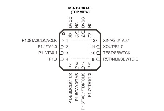
MSP430G2201IRSA16 characteristics include:
Low cost, I bought 130 of these for $0.38 AUD each in August 2021, during the ‘Great MCU Shortage’ from my preferred suppliers, who list 500 are still in stock today 15 Feb 2022.
Among the lowest of low power MCU’s available today
Low supply voltage range, 1.8 to 3.6v
Five power saving modes
Spy-by Wire and JTAG interface
Self contained including clocks
2KB Flash. That’s right, it’s too small to even run the target hosted Mecrisp Forth! However it is perfect for a Tethered Forth!
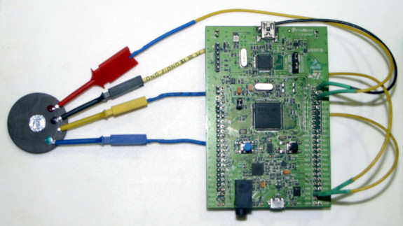
Demo Board Tethered To Host
For more information on how to connect these boards, please see here.
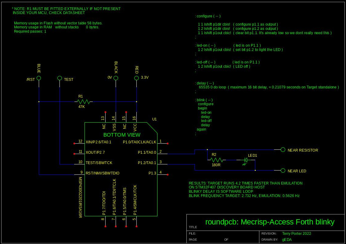
Demo Board Schematic
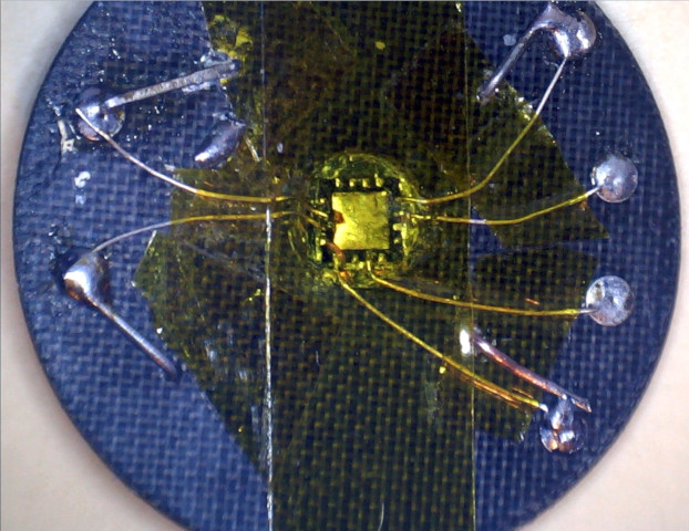
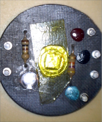
Demo Board
Handmade using recycled teflon composite substrate, previously used in faulty 5Ghz wifi antennas, along with sturdy and reliable turret pins. Construction details are explained in THIS LINK
The How
The C Programming Language
I assume we are all familiar with how to create embedded projects with C ?
Using C, we create a project, write and run a source file thru a C compiler, on a PC host, usually running a Free Unix OS and we obtain a binary image that runs on the target MCU.
If the project doesn’t do what we want, crashes etc, we review our source file, perhaps run a interactive debugger like GDB and repeat the process until it all works as designed. This process can take many iterations, perhaps hundreds, with much reading and re-reading of the MCU technical manual etc.
Forth
Mecrisp-Across Forth does everything the C compiler above does including generate a small binary image that runs on the target MCU.
However this is where the development process deviates wildly, and for the better.
You have probably heard about Forth, you probably also know that Forth is interactive, that is, you can talk to the MCU while it’s running, make GPIO pins change state, light that LED, turn it off, read MCU register values, test out that your hardware is connected properly and verify it does what the data sheet claims it does, all in real-time.
Because Mecrisp-Across is also interactive, the C “edit, compile, flash, test, repeat” process becomes the Forth “edit, test, repeat” process. It’s tons easier and much, much faster.
Forth is it’s own interactive real-time debugger !
There are two types of Forth, ‘Hosted’ and ‘Tethered’
Because the target is a MSP430G2201IRSA16 with only 2KB of flash, we need a Tethered Forth for this project
Type |
Name |
Target |
Description |
Forth Target Flash Memory Required (minimum) |
|---|---|---|---|---|
Hosted |
Mecrisp-Stellaris |
STM32xx |
Resides in the MCU target flash memory |
20KB |
Hosted |
Mecrisp |
MSP430xx |
Resides in the MCU target flash memory |
11KB |
Tethered |
Mecrisp-Across |
MSP430xx |
Resides in the Host only |
zero |
Mecrisp-Across is a tethered Forth, that means the Host is connected to the Target with a four wire cable, or tether during development. When the project is finished, the Target is then disconnected from the Tether and it runs standalone doing what the project designed it to do.
The programmer talks to the Host using a serial terminal such as Picocom from the PC, over a USB cable.
The terminal screen provides a way to interactively communicate with the target MCU and to also upload source files from the PC.
The Tether
Mecrisp-Across is a Tethered Forth, how does that work, what’s the low-down ?
Mecrisp-Across
Is a Forth program that runs under Mecrisp-Stellaris on the Host, a STM32F407 Discovery Board.
Is an advanced, optimising cross compiler, written in Forth that produces a bootable binary for the MSP430xx.
Is an emulator (about four times slower than machine code running directly on the target).
Looks just like Mecrisp-Stellaris until the ‘target’ Word is executed, then it looks like Mecrisp on a MSP430
Controls the Target using JTAG over the Tether. It has complete ‘remote control’ of the Target.
Mecrisp-Across Does Not
Run on the Target. In fact during interactive mode, the Target CPU is held in reset, it’s brain dead!
Use any Target Resources, including Flash or Ram.
The Emulator
Why does Mecrisp-Across have a emulator ?
Because the user never actually communicates with the Target CPU directly at any time because it is held in reset, it’s brain dead. Mecrisp-Across does this so it can access everything in the chip using JTAG, (that means memory, registers, peripherals etc) without the CPU interfering.
Because that’s what CPU’s do, they interfere … ask any programmer?
When a Forth commands reads a Target register like so:
DCOCTL c@ bin8. 01100000 ok.
The emulator, via the JTAG remote control ‘Tether’ reads the DCOCTL register and displays it in the emulator for the user to read.
It’s a bit confusing to the Forth user.
After developing on the MSP430 this way, I could swear that I was indeed communicating with the chip directly, and like the ELIZA AI program of old, I could swear that the Target was alive! I guess you have to experience it for yourself. Matthias has built something truly clever here.
Summary
Emulation mode is used for project development, it’s exactly the same as you would develop a project using a on-chip Forth.
Note
Even tho the emulator is about four times slower than the actual chip, in human terms the response is instant.
The Compiler
Why does Mecrisp-Across have a compiler ?
Because even after the project has been developed, the Target chip still has nothing in it. If the flash and ram were blank when you connected it, they’re still blank now.
Remember, the Target never had Forth on it, it was held in reset the whole time and it’s not about to get a Forth on it now because the flash memory in this MSP430G2201IRSA16 chip is still only 2KB. It was never big enough to have its own Forth.
This chip was made to run a machine language binary image, end of story.
What’s more, it was made to run a efficient machine language binary image, something a good programmer might write using a good assembly language program.
That might be you, but it’s sure as hell not me, I’m a electronics technician not a programmer, I need help here!
That’s where Mecrisp-Across comes in.
- Mecrisp-Across is possibly one of the strongest optimizing Forth cross compilers you have ever seen. Out of the box, it does:
Constant folding
Register allocation for both data and return stack
Dead code elimination (imagine a constant feed into case)
Register allocation across control structures
Determination which definitions are in use,
Automatic inlining of definitions used one time only
Interrupt handler framing depending on register usage
Mecrisp-Across now takes the boring Forth blinky program project I just made and tested interactively in the emulator and compiles it into a binary image.
But that’s not all … Mecrisp-Across also flashes that binary image to the chip, over the Tether along with the necessary startup and interrupt vector for a turnkey system.
In other words, the target LED now blinks with only power applied and the tether severed completely.
The project is now finished!
The Quick Test
Assuming we have a MSP430 connected to the Host via the four wire tether. The Host is connected to USB POWER a PC via a USB cable to CN1, and a SERIAL TERMINAL on the PC via a USB cable to CN5 (next to the big black audio socket) on the Host, now let’s do a quick test to make sure everything is working ?
Is Mecrisp-Across installed and working on the Host ?
Is the Host Flashed with “mecrisp-stellaris-stm32f407-with-mecrisp-across.bin” size = 131072 bytes ?
on the PC in a xterm run:
picocom -b 115200 /dev/cuaU1 --hangup --imap lfcrlf,crcrlf --omap delbs,crlf --send-cmd "cat"
Do you see something like this in the terminal ?
picocom v3.1
port is        : /dev/cuaU1
flowcontrol    : none
baudrate is    : 115200
parity is      : none
databits are   : 8
stopbits are   : 1
escape is      : C-a
local echo is  : no
noinit is      : no
noreset is     : no
hangup is      : yes
nolock is      : no
send_cmd is    : cat
receive_cmd is : rz -vv -E
imap is        : crcrlf,lfcrlf,
omap is        : crlf,delbs,
emap is        : crcrlf,delbs,
logfile is     : none
initstring     : none
exit_after is  : not set
exit is        : no
Type [C-a] [C-h] to see available commands
Terminal ready

( I hit the enter key here ) ok.
If you do, then PC –> Host is working properly.
Is The Host Talking To The Target ?
From the Picom terminal after booting the STM32F4 Discovery Board above:
+jtag
This tells Mecrisp-Across to connect the Target via JTAG. The “F201” means that Mecrisp-Across has detected my chip, the MSP430G2201. According to Matthias, a JTPG issue prevents fetching more than the last three characters of the Chip type. I’m not sure where the “F” comes from.
+jtag
You should see:
Chip detected: F201 ok.
Target
Switch to Target emulation
target
List all the Words (subrotines) on the Target Emulator.
list
You should see something like this:
u.r .r ud.r d.r rtype u. . d. ud. (d.) #> #s # sign hold <# output-base hld BUF BUF0 maximum-number-length
d0= type spaces bin. hex. hex-digit-emit .digit space cr uart-init emit key emit? key? BCSCTL2 BCSCTL1 DCOCTL
BCSCTL3 P2SEL2 P1SEL2 P2REN P2SEL P2IE P2IES P2IFG P2DIR P2OUT P2IN P1REN P1SEL P1IE P1IES P1IFG P1DIR P1OUT
P1IN CALBC1_1MHZ CALDCO_1MHZ CALBC1_8MHZ CALDCO_8MHZ CALBC1_12MHZ CALDCO_12MHZCALBC1_1MHZ CALBC1_16MHZ
CALDCO_16MHZ P3SEL2 P3SEL P3DIR P3OUT P3IN P3REN IFG2 IFG1 IE2 IE1 UCA0TXBUF UCA0RXBUF UCA0STAT UCA0MCTL UCA0BR1
UCA0BR0 UCA0CTL1 UCA0CTL0 UCB0TXBUF UCB0RXBUF UCB0STAT UCB0BR1 UCB0BR0 UCB0CTL1 UCB0CTL0 ADC10SA ADC10MEM
ADC10CTL1 ADC10CTL0 ADC10AE0 ADC10DTC1 ADC10DTC0 TLV_CHECKSUM TLV_DCO_30_LEN TLV_DCO_30_TAG TLV_ADC10_1_LEN
TLV_ADC10_1_TAG UCB0I2CSA UCB0I2COA UCB0TXBUF UCB0RXBUF UCB0STAT UCB0I2CIE UCB0BR1 UCB0BR0 UCB0CTL1 UCB0CTL0
TA0CCR2 TA0CCR1 TA0CCR0 TA0R TA0CCTL2 TA0CCTL1 TA0CCTL0 TA0CTL TA0IV TA1CCR2 TA1CCR1 TA1CCR0 TA1R TA1CCTL2
TA1CCTL1 TA1CCTL0 TA1CTL TA1IV CAPD CACTL2 CACTL1 WDTCTL UCA0TXBUF UCA0RXBUF UCA0STAT UCA0MCTL UCA0BR1 UCA0BR0
UCA0CTL1 UCA0CTL0 UCA0IRRCTL UCA0IRTCTL UCA0ABCTL FCTL3 FCTL2 FCTL1 mod / /mod */ */mod fm/mod sm/rem sgn m* dabs
dnegate s>d abs um/ mod divstep um* mulstep (next) (for) j i loop unloop leave ?do do endcase endof of case ?dup
true false negate * arshift rshift lshift cbit@ bit@ cxor! cbis! cbic! c! xor! bis! bic! +! ! flush c@ @ <= > u<= u>
0<> 0< 0= >= < u>= u< <> = d- d+ 2- 2+ 1- 1+ not bic - and xor or + wakeup dint eint lpm4 lpm3 lpm2 lpm1 lpm0
d2/ dshr d2* dshl ror rol >< 2/ shr 2* shl 2swap 2dup 2drop rdrop tuck nip over -rot rot r> r@ >r drop swap dup
buffer: variable constant cura see [char] char list words .s decimal binary hex endcreate create does>
(does>-newdef) (does>) <builds postpone ; : exit repeat while else then if ahead until again begin literal
compile, , ] [ host \ ( 7-foldable 6-foldable 5-foldable 4-foldable 3-foldable 2-foldable 1-foldable 0-foldable
inline immediate
OK! All the basics are working!
Test The Target LED
Now we need to test the Target board by lighting the LED.
chip: MSP430G2201IRSA16R but any MSP430 should work.
P1.2: LED +ve
P1.1: LED 0v via 150R resistor
Utility
First we will upload this small utility which will display any number up to 255 as a binary number, via pasting everything into the Picocom terminal.
: bin8. ( x -- 8 bit display )  \ Display a 8 bit number as bits
   8 lshift                     \ move data 8 bits to left ... why ?
      8 0 do                    \ cycle thru 8 bits
           dup                  \ copy data value for 2* to use
           0<                   \ give true (1) if number is negative, false (0) otherwise (consumes input)
           1 and                \ 1 1 AND = 1, 0 1 AND = 0. This is the binary output value
           [char] 0 +           \ gives ascii code of ascii "0" (48)
           emit                 \ print bit value
           2*                   \ select next bit to the left to test
      loop
   drop
   space
;
Test:
255 bin8. 11111111 ok.
Configuration
Set p1.1 and p2.1 as outputs
Run this first to see the default value in p1dir
  p1dir c@ bin8.
    00000000 ok

1 1 lshift p1dir cbis!       \ configure p1.1 as output
  test it
     p1dir c@ bin8. 00000010 ok.

1 2 lshift p1dir cbis!       \ configure p1.2 as output
  test it
     p1dir c@ bin8. 00000110 ok.
Set P1.1 Low
Test p1out register
  p1out c@ bin8. 00000000 ok.

1 1 lshift p1out cbic!    \ clear bit p1.1. It's already low so we dont really need this

1 2 lshift p1out cbis!    \ set bit p1.2 to light the LED, does it work ?
1 2 lshift p1out cbic!    \ clear bit p1.2 to turn the LED off. does it work ?
Ok, the Host and the Target are working, the LED is wired correctly, we are ready to proceed to the Blinky!
The Blinky Sourcecode
This one file controls everything, it switches modes and finally compiles and flashes the binary image to the target.
blinky.fs
new       \ New Forth source code to be cross compiled
+jtag     \ Activate JTAG mode
target    \ Emulate the target ( We never leave the Host )

: configure ( -- )

   1 1 lshift p1dir cbis!  \ configure p1.1 as output
   1 2 lshift p1dir cbis!  \ configure p1.2 as output
   1 1 lshift p1out cbic!  \ clear bit p1.1. It's already low so we dont really need this
;

: led-on ( -- )                   \ led is on P1.1
   1 2 lshift p1out cbis!  \ set bit p1.2 to light the LED
;

: led-off ( -- )          \ led is on P1.1
   1 2 lshift p1out cbic!  \ LED off
;


: delay ( -- )
    65535 0 do loop       \ maximum 16 bit delay, = 0.21079 seconds on Target standalone
;

: blink ( -- )
   configure
   begin
      led-on
      delay
      led-off
      delay
  again
;

host
$FFFE vector blink crosscompile flashtarget -jtag run
Output
Memory usage in Flash without vector table 58 bytes.
Memory usage in RAM   without stacks       0 bytes.
Required passes: 1
Summary
Initial Commands
As commented.
new       \ New Forth source code to be cross compiled, clear any previous code, start again. MUST be used to start new Forth code.
+jtag     \ Activate JTAG mode (the tether unbilical)
target    \ Emulate the target ( We never leave the Host )
Configure
This configures the ports as desired. Note this blinky is a bit different in that it uses TWO port pins to drive the LED. One pin supplies the positive voltage end the other supplies 0V. Usually one drives a LED using one GPIO only, the 0v LED pin connects to 0v, not a GPIO pin. I have designed the blinky this way so I can reverse bias the LED in another project which measure the local light intensity.
: configure ( -- )

   1 1 lshift p1dir cbis!  \ configure p1.1 as output
   1 2 lshift p1dir cbis!  \ configure p1.2 as output
   1 1 lshift p1out cbic!  \ clear bit p1.1. It's already low so we dont really need this
;

... the middle code should be self evident.
Final Commands
Switch Mecrisp-Across back to Host mode
host
Set the $FFFE boot vector to run the blink Word
This is equivalent to the Mecrisp-Stellaris “init” turnkey Word. The blink Word is like the C “Main” function and it must call all sub Words as shown in the source.
$FFFE vector blink
Croscompile your Forth code into a compact machine code binary image
crosscompile
Flash the Target chip over JTAG
flashtarget
Turn OFF the JTAG
This releases the RESET pin to let the Target run the binary image standalone.
-jtag
Run The Image
The LED now blinks!
run
Assuming your LED is now blinking, everything is working!
Mecrisp-Across Final Summary Output
This tells you how much Flash and Ram will be used for your binary image. I think 58 bytes is very small for my Blinky program.
Memory usage in Flash without vector table 58 bytes.
Memory usage in RAM   without stacks       0 bytes.
Required passes: 1
ALL DONE!
Finished - Some Extras
There are a few extra commands you can run which allow greater analysis of the Mecrisp-Across output.
see led-on
Adding this command in the source ( or in interactive mode) allows investigation of the generated source, for instance:
see led-on
\ : led-on
\ 00008CB0 : 0000 : $00000004
\ 00008CBC : 0000 : $00000021
\ 00008CC8 : 0000 : cbis!
\ 00008CD4 : 0000 : ;
host
Revert to host mode (mecrisp-Across)
disimage
Show the assembly language of the final binary image.
\ F800: 4307  mov.w #0h, r7
\ F802: 4338  mov.w #FFFFh, r8
\ F804: 5317  add.w #1h, r7
\ F806: 9807  cmp.w r8, r7
\ F808: 23FD  jnz F804
\ F80A: 4130  mov.w @r1+, r0
\
\ F80C: 40B2  mov.w #5A80h, &120h
\ F80E: 5A80
\ F810: 0120
\ F812: 4031  mov.w #280h, r1
\ F814: 0280
\ F816: 4034  mov.w #260h, r4
\ F818: 0260
\ F81A: D3E2  bis.b #2h, &22h
\ F81C: 0022
\ F81E: D2E2  bis.b #4h, &22h
\ F820: 0022
\ F822: C3E2  bic.b #2h, &21h
\ F824: 0021
\ F826: D2E2  bis.b #4h, &21h
\ F828: 0021
\ F82A: 12B0  call.w #F800h
\ F82C: F800
\ F82E: C2E2  bic.b #4h, &21h
\ F830: 0021
\ F832: 12B0  call.w #F800h
\ F834: F800
\ F836: 3FF7  jmp F826
\ F838: 3FFF  jmp F838
hexdump
This is a Intel Hexfile of the blinky program which can be used in a MSP430 programmer to flash other MSP430 chips.
\ :10F800000743384317530798FD233041B240805ACD
\ :10F8100020013140800234406002E2D32200E2D273
\ :10F820002200E2C32100E2D22100B01200F8E2C2BD
\ :10F830002100B01200F8F73FFF3FFFFFFFFFFFFF7F
\ :10FFF000FFFFFFFFFFFFFFFFFFFFFFFFFFFF0CF80B
\ :00000001FF
Summary and print of my blinky file with commented out results
\ Program Name: msp430.blinky.fs
\ Date: 13 Feb 2022
\ Copyright 2022  t.porter licensed under the GPL
\ For Mecrisp-Across by Matthias Koch
\ http://mecrisp.sourceforge.net/  features:
\ * Constant folding
\ * Register allocation for both data and return stack
\ * Dead code elimination (imagine a constant feed into case)
\ * Register allocation across control structures
\ * Determination which definitions are in use
\ * Automatic inlining of definitions used one time only
\ * Interrupt handler framing depending on register usage
\
\ chip: MSP430G2201IRSA16R
\ Target: 2.3720 Hz, 50% duty cycle
\ Host:   0.5626 Hz, 50% duty cycle
\ Target runs 4.2 times faster than Host Emulation


new       \ New Forth source code to be cross compiled
+jtag     \ Activate JTAG mode
target    \ Emulate the target ( We never leave the Host )


: configure ( -- )

   1 1 lshift p1dir cbis!  \ configure p1.1 as output
   1 2 lshift p1dir cbis!  \ configure p1.2 as output
   1 1 lshift p1out cbic!  \ clear bit p1.1. It's already low so we dont really need this
;

: led-on ( -- )                   \ led is on P1.1
   1 2 lshift p1out cbis!  \ set bit p1.2 to light the LED
;

: led-off ( -- )          \ led is on P1.1
   1 2 lshift p1out cbic!  \ LED off
;


: delay ( -- )
    65535 0 do loop       \ maximum 16 bit delay, = 0.21079 seconds on Target standalone
;

: blink ( -- )
   configure
   begin
      led-on
      delay
      led-off
      delay
  again
;

 see configure
 \ : configure
 \ 00008BFC : 0000 : $00000002
 \ 00008C08 : 0000 : $00000022
 \ 00008C14 : 0000 : cbis!
 \ 00008C20 : 0000 : $00000004
 \ 00008C2C : 0000 : $00000022
 \ 00008C38 : 0000 : cbis!
 \ 00008C44 : 0000 : $00000002
 \ 00008C50 : 0000 : $00000021
 \ 00008C5C : 0000 : cbic!
 \ 00008C68 : 0000 : ;
 see led-on
 \ : led-on
 \ 00008CB0 : 0000 : $00000004
 \ 00008CBC : 0000 : $00000021
 \ 00008CC8 : 0000 : cbis!
 \ 00008CD4 : 0000 : ;
 see led-off
 \ : led-off
 \ 00008D1C : 0000 : $00000004
 \ 00008D28 : 0000 : $00000021
 \ 00008D34 : 0000 : cbic!
 \ 00008D40 : 0000 :
 see delay
 \ : delay
 \ 00008D88 : 0000 : $0000FFFF
 \ 00008D94 : 0000 : $00000000
 \ 00008DA0 : 0000 : swap
 \ 00008DAC : 0000 : >r
 \ 00008DB8 : 0000 : >r
 \ 00008DC4 : 0000 : <--
 \ 00008DFC : 0000 : r>
 \ 00008E08 : 0000 : $00000001
 \ 00008E14 : 0000 : +
 \ 00008E20 : 0000 : r@
 \ 00008E2C : 0000 : >r
 \ 00008E38 : 0000 : dup
 \ 00008E44 : 0000 : r>
 \ 00008E50 : 0000 : swap
 \ 00008E5C : 0000 : >r
 \ 00008E68 : 0000 : =
 \ 00008E74 : 0000 : 0-Branch $00008DC4
 \ 00008E80 : 0000 : r>
 \ 00008E8C : 0000 : drop
 \ 00008E98 : 0000 : r>
 \ 00008EA4 : 0000 : drop
 \ 00008EB0 : 0000 : ;
 see blink
 \ : blink
 \ 00008EF8 : 0000 : configure
 \ 00008F04 : 0000 : <--
 \ 00008F3C : 0000 : led-on
 \ 00008F48 : 0000 : delay
 \ 00008F54 : 0000 : led-off
 \ 00008F6SLAU1440 : 0000 : delay
 \ 00008F6C : 0000 : Branch $00008F04
 \ 00008F78 : 0000 : ;
host
disimage
 \ F800: 4307  mov.w #0h, r7
 \ F802: 4338  mov.w #FFFFh, r8
 \ F804: 5317  add.w #1h, r7
 \ F806: 9807  cmp.w r8, r7
 \ F808: 23FD  jnz F804
 \ F80A: 4130  mov.w @r1+, r0
 \
 \ F80C: 40B2  mov.w #5A80h, &120h
 \ F80E: 5A80
 \ F810: 0120
 \ F812: 4031  mov.w #280h, r1
 \ F814: 0280
 \ F816: 4034  mov.w #260h, r4
 \ F818: 0260
 \ F81A: D3E2  bis.b #2h, &22h
 \ F81C: 0022
 \ F81E: D2E2  bis.b #4h, &22h
 \ F820: 0022
 \ F822: C3E2  bic.b #2h, &21h
 \ F824: 0021
 \ F826: D2E2  bis.b #4h, &21h
 \ F828: 0021
 \ F82A: 12B0  call.w #F800h
 \ F82C: F800
 \ F82E: C2E2  bic.b #4h, &21h
 \ F830: 0021
 \ F832: 12B0  call.w #F800h
 \ F834: F800
 \ F836: 3FF7  jmp F826
 \ F838: 3FFF  jmp F838
hexdump
 \ :10F800000743384317530798FD233041B240805ACD
 \ :10F8100020013140800234406002E2D32200E2D273
 \ :10F820002200E2C32100E2D22100B01200F8E2C2BD
 \ :10F830002100B01200F8F73FFF3FFFFFFFFFFFFF7F
 \ :10FFF000FFFFFFFFFFFFFFFFFFFFFFFFFFFF0CF80B
 \ :00000001FF
$FFFE vector blink crosscompile flashtarget -jtag run
 \ Memory usage in Flash without vector table 58 bytes.
 \ Memory usage in RAM   without stacks       0 bytes.
 \ Required passes: 1
Running Mecrisp-Across on a PC
Do you recall I mentioned at the start of this article that the Host Boards (or even the STM43F407 MCU) may not be available right now?
The good news is that even without the Host Board, you can still run Mecrisp-Across on a Unix PC, generate the Target Binary Image, and use a separate programmer such as the TI FET type programmer board such as a MSP-EXP430G2 to flash the chip :)
All you will lose is the interactivity to the Target, which admittedly is the whole point of Forth. At this point it’s equivalent to GCC, more or less.
** This completes the Demo, you can find lots more information on this site, via the index, ‘whats new’ etc.**
Author: T.Porter, about 722 lines, and 4500 words.