MSP430G2201IRSA16R
Features for the MSP430G2201
Low Supply-Voltage Range: 1.8 V to 3.6 V
- Ultralow Power Consumption
Active Mode: 220 µA at 1 MHz, 2.2 V
Standby Mode: 0.5 µA
Off Mode (RAM Retention): 0.1 µA
Five Power-Saving Modes
Ultrafast Wake-Up From Standby Mode in Less Than 1 µs
16-Bit RISC Architecture, 62.5-ns Instruction Cycle Time
16-Bit Timer_A With Two Capture/Compare Registers
Brownout Detector
Serial Onboard Programming, No External Programming Voltage Needed, Programmable Code Protection by Security Fuse
On-Chip Emulation Logic With Spy-Bi-Wire Interface
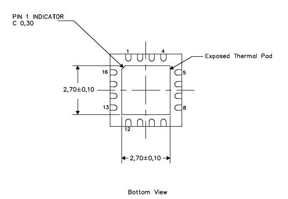
Available in a 14-Pin Plastic Small-Outline Thin Package (TSSOP) (PW), 14-Pin Plastic Dual Inline Package (PDIP) (N), and 16-Pin QFN (RSA
Clocks: LF, DCO, VLO
10 I/O
Footprint
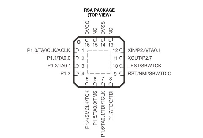
Port Pins
Ports Available |
Pin |
Description |
|---|---|---|
P1.0 |
1 |
|
P1.1 |
2 |
|
P1.2 |
3 |
|
P1.3 |
4 |
|
P1.4 |
5 |
|
P1.5 |
6 |
|
P1.6 |
7 |
|
P1.7 |
8 |
|
P2.6 |
12 |
|
P2.7 |
11 |
Timer-A Pins
Timer A |
Pin |
Description |
|---|---|---|
ACLK |
1 |
ACLK signal output |
TAO.0 |
2 |
Timer0_A, capture: CCI0A input, compare: Out0 output |
TAO.1 |
3 |
Timer0_A, capture: CCI1A input, compare: Out1 output |
SMCLK |
5 |
SMCLK signal output |
TCK |
5 |
JTAG test clock, input terminal for device programming and test |
TAO.0 |
6 |
Timer0_A, capture: CCI0A input, compare: Out0 output |
TMS |
6 |
JTAG test mode select, input terminal for device programming and test |
TAO.1 |
7 |
Timer0_A, capture: CCI1A input, compare: Out1 output |
TDI/TCLK |
7 |
JTAG test data input or test clock input during programming and test |
TDO/TDI |
8 |
JTAG test data output terminal or test data input during programming and test |
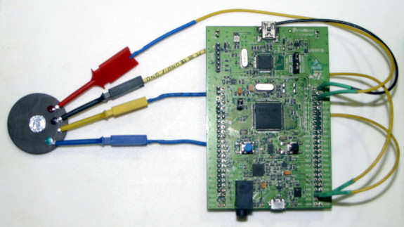
Round Test PCB
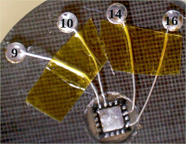
Target Connection Table
The STM32F4 Discovery board must be connected to the MSP430G2201IRSA16R target as per this Connection Table.
Pins |
Test Clip Color |
MSP430 Target Pin |
|---|---|---|
PC-8 |
BLUE |
RST - pin 9 |
PC-9 |
YELLOW |
TEST - pin 10 |
GND |
BLACK |
GND - pin 14 |
3.3V |
RED |
VCC - pin 16 |
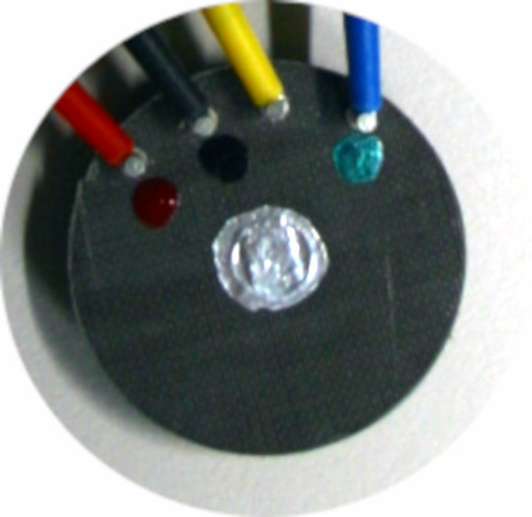
Target Connected To Host