> What’s New ? <
Msp430f2101idwr
Intro
Purchased: 1000 units from Arrow.com on 22 Oct 2023 for $0.10 each inc shipping. Use with: Mecrisp-Across for all small sensor applications.
Specs
1KB + 256B Flash Memory, 128B RAM
16-Bit Timer_A With Three Capture/Compare Registers
On-Chip Comparator for Analog Signal Compare Function or Slope Analog-to-Digital (A/D) Conversion
Pinouts
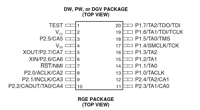
Functional
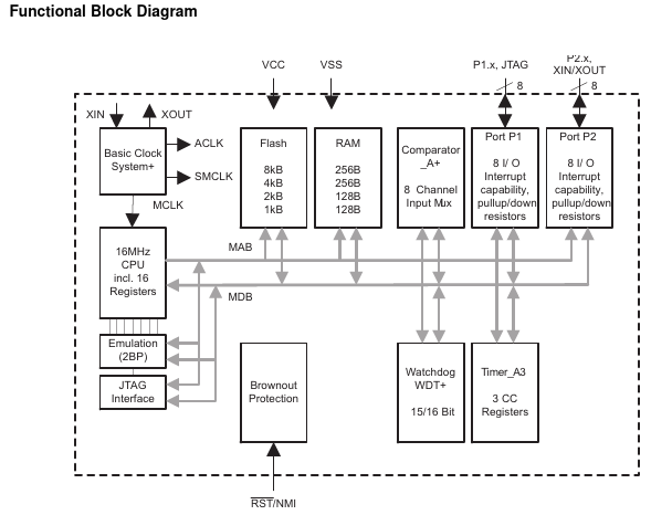
Description
The MSP430F2101 is an ultra-low-power mixed signal microcontroller from Texas Instruments. It is part of the MSP430x21x1 series and comes with a built-in 16-bit timer, versatile analog comparator, and sixteen I/O pins ti.com.
The MSP430F2101 is typically used in applications that involve sensor systems. These systems capture analog signals, convert them to digital values, and then process the data for display or for transmission to a host system. The analog comparator in the MSP430F2101 provides slope A/D conversion capability, which is useful in these applications. Another area of application is as a stand-alone RF sensor front end ti.com.
Here is a brief overview of the main features of the MSP430F2101:
16-bit Timer: This feature allows the microcontroller to keep track of time intervals, which is useful in various applications such as timing events or generating PWM signals.
Analog Comparator: This feature is used to compare two analog signals. It can be used to detect changes in analog signals, which is useful in applications such as detecting the presence of a sensor or detecting changes in the value of a sensor.
Sixteen I/O Pins: These pins can be used to interface with other components or peripherals. They can be configured as digital inputs or outputs, or as analog inputs.
Ultra-low-power: The MSP430F2101 is designed to be ultra-low-power, making it suitable for battery-powered applications.
Mixed Signal: This means that the microcontroller can handle both analog and digital signals, which is useful in applications that require both types of signals.
Low Power
The MSP430F2101 microcontroller achieves ultra-low power consumption through a combination of hardware and software optimizations.
Hardware Optimizations
The MSP430F2101 is designed with power-saving features. For instance, it has a low-power mode that reduces the power consumption of the microcontroller when it is not performing any tasks. This mode can be entered and exited using software commands, allowing the microcontroller to save power when it is not in use and wake up when it needs to perform a task.
Software Optimizations
The software running on the MSP430F2101 can also be optimized to reduce power consumption. For example, the software can be designed to put the microcontroller into a low-power mode when it is waiting for an event to occur. This can significantly reduce the power consumption of the microcontroller, especially in applications where it spends a lot of time waiting for events.
Dynamic Voltage Scaling (DVS)
The MSP430F2101 supports dynamic voltage scaling, which allows the microcontroller to adjust its operating voltage based on the current power requirements. This can help to reduce power consumption when the microcontroller is performing tasks that require less power.
Sleep Mode
The MSP430F2101 supports a sleep mode, which reduces the power consumption of the microcontroller by turning off the clock and other power-consuming components. The microcontroller can be woken up from sleep mode by an interrupt or a reset.
Power-Saving Peripherals
The MSP430F2101 also includes power-saving peripherals, such as a low-power timer and a low-power comparator. These peripherals can be used to perform tasks with minimal power consumption.
These features and optimizations allow the MSP430F2101 to operate with ultra-low power consumption, making it suitable for battery-powered applications ti.com.
Comparator
The reference voltage for the comparator in the MSP430F2101 microcontroller is set by the CAREFx bits in the CACTL1 register. The CAREFx bits are defined as follows:
CAREF0: 0.25 Vcc
CAREF1: 0.5 Vcc
CAREF2: 1.25 Vcc
CAREF3: 2.5 Vcc
To change the reference voltage, you need to modify the CACTL1 register. For example, to set the reference voltage to 1.25 Vcc, you would use the following code:
CACTL1 = CAREF2 + CAON;
This sets the CAREF2 bit and turns the comparator on with the CAON bit.
Please note that the actual reference voltage is not exactly the same as the value defined by the CAREFx bits. The actual reference voltage is determined by the internal voltage reference generator (VREF) of the microcontroller. The CAREFx bits define the ratio of the VREF voltage to the reference voltage. For example, if CAREF0 is set, the reference voltage is 0.25 * VREF.
Also, keep in mind that changing the reference voltage will affect the output of the comparator. The output will be set (logic high) if the voltage on the positive input is greater than the reference voltage, and reset (logic low) otherwise e2e.ti.com.
CACTL1 register
The CACTL1 register is a special function register in the MSP430F2101 microcontroller that controls the operation of the analog comparator. You can access this register directly in your code using the CACTL1 identifier.
Here is an example of how to access the CACTL1 register:
#include <msp430.h>

int main(void)
{
    CACTL1 = CAREF0 + CAON;  // Set reference voltage to 0.25 Vcc and turn on the comparator
    // ... rest of your code ...
}
In this code, CACTL1 = CAREF0 + CAON; sets the CAREF0 bit and the CAON bit in the CACTL1 register. The CAREF0 bit sets the reference voltage to 0.25 Vcc, and the CAON bit turns on the comparator.
Please note that you need to include the msp430.h header file at the beginning of your code to use the CACTL1 identifier. This header file contains the definitions for all the special function registers in the MSP430F2101 microcontroller, including CACTL1 e2e.ti.com.