It’s All About Timing
Abstract
The importance of timing in both Interactive and Target Modes.
Terms
Host - 32 bit STM32F407 Discovery Board running Mecrisp-Stellaris.
Target - Texas Instruments MSP430 MCU. Note: The MCU is totally STOPPED in Interactive Mode.
Emulator/Interactive - Mecrisp-Across is a Forth program running on Mecrisp-Stellaris.
Tether - A four wire JTAG cable that connects the Target and Host.
Terminal - A serial terminal emulator running on the users PC and connected to the Host via USB.
Description
Mecrisp-Across is a 16 bit MSP430 emulator running on a 32 bit Mecrisp-Stellais Forth, hosted on a 32 bit STM32F407 Discovery Board clocked at 168 MHz. The emulator transfers hardware data from a real MSP430 Target chip in near real time to provide Forth console interactivity.
Got it ?
What’s The Problem ?
TA0CTL @ bin1.
As an example, consider the above where the Timer A0 Counter Control Register value is fetched from the Target and displayed on the user Terminal.
A number of processes are required for this transfer to occur.
The user enters the Forth statement above into the Terminal.
The Emulator constructs the necessary inquiry protocol to obtain the Target TAOR register value.
The Emulator requests the TA0CTL register value from the Target over the JTAG tether.
The Target supplies the value to the Host.
The Emulator then displays this value on the user Terminal. The code below shows the value ‘0000000100000001’ listed underneath a bit position legend of 0 - 15 for easy decoding using the Technical Manual as below.
111111
5432109876543210
0000000100000001
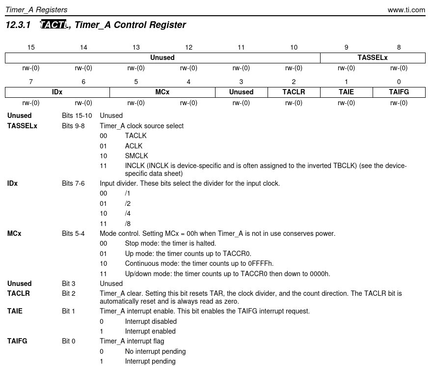
Looking in the SLAU144J technical manual and decoding the data above indicates that
TAIFG = %1, so the Timer_A interrupt flag = PENDING
TASSEL0 = %01, so the Timer_A clock source = ACLK.
This is right now, in near real time inside the actual MSP430 Target chip.
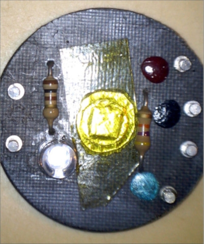
The chip In This Board
I say near real time because there is a time overhead for the JTAG protocol exchanges because everything takes some appreciable quantity of time.
The significance here is that when fetching this same value on the MCU as part of a turnkey program, the final stage of the development, the delay will be MUCH LESS because it’s not over a slow JTAG bus, but using the MCU internal high speed data buses.
Human Speed
When fetching MCU register information or writing new data to the MCU registers, the JTAG overhead is not normally a problem in a Interactive Forth system. The developer will test things such as “Is the LED lighting when ‘LED-ON’ is entered or is RELAY-1 operating when “PUMP-ON” is entered ?
Testing and development normally proceed at the humans pace during development.
Computer Speed
Small embedded systems make extensive use of accurate (blocking) delays implemented in software. This is because the real world is so slow in comparison to even the slowest of microprocessor clocks, therefore the microprocessor must be slowed down much of the time.
For instance a LED may be used to indicate a shaft is turning by blinking every time a one microsecond pulse is received. However the one microsecond pulse is itself too short for human observation, so it needs to be extended to 50 milliseconds with a delay program.
: delay ( -- )
   65535 0 do loop       \ maximum 16 bit delay, = 0.21079 seconds on Target standalone
;
Timing is The Problem
This is a software blocking delay, it causes the MCU to loop for 0.21079 seconds on a untethered, standalone Target. See this Blinky article for more details.
But when this same program is run on the Host in Interactive mode, the delay is 4.2 times longer or 0.885318 seconds.
I assume this timing difference is due to two factors:
JTAG protocol overheads
The Host speed, because it is actually running the delay software computation above not the Target. The Target cpu is held in reset the entire time in Interactive mode.
This timing discrepancy causes the developer serious problems because programs written and debugged in Interactive mode are destined to end up running on the Target as a binary image WITH NO CHANGES TO THE SOFTWARE.
Maintaining different values for delays running on the Host or Target are impractical, error prone, and time consuming, a better solution is needed.
The Solution ?
We can’t do anything about the JTAG protocol communication delay overhead, but we can remove the discrepancy between computational speeds on Host and Target by using a HARDWARE TIMER on the Target which has stable RC clock and will keep the same time in either mode. This hardware timer can tell us when time is up.
Fortunately all MSP430’s come with at least one hardware timer, TA0, which has a pollable flag that can be reset by software.
Using digital oscilliscope pictures made by a program that uses the hardware timer to turn a LED ON, and a software timer to turn the LED off, we can compare the timing variations on both the Target and Host.